How prototype Arduino-based fan controller and break 3 boards
The summer came and cooling of different systems become bigger issue than during the winter time.
How do we cool down equipment normally? Just using fan. And charging stations are not excluded.
Simple way is to turn the fan on when temperature reaches some threshold and turn off, when it is below.
The approach will work if the system is small and the fan is silent.
What if we need to control fan which creates significant noise when running at full speed? Well, try to reduce speed, when temperature only slightly above threshold, and run the full speed when it significantly above.
Let's try to implement it using Arduino.
Thinking naturally, we should control the voltage applied to the fan. But Arduino can not provide regulated voltage output. So we skip this approach, and start directly with PWM
PWM basics
Idea of PWM conrol is that load is either fully turned on or fully off. Switching frequency is high enough and end result is indistinguishable from steady partial performance.
The performance of the load will be proportional to the "duty cycle".
Arduino PWM
Unfortunately, Arduino PWM pins provide only 40mA at 5 volts which means only 200mW loads can be connected directly (for example LEDs can work).
If I need more power, or higher voltage, e.g. 12-volt motor, I need to add PWM-driver circuitry to the output. PWM-drive is basically an amplifier of the signal.
Connecting MOSFET
The first choice for such purpose, would be a MOSFET transistor. At a first glance it is the perfect for this purpose: it is controlled by voltage (comparing to current in traditional BJT-transistors), and can handle high currents.
Let's try it.
Theoretically the standard MOSFETs should be controlled by 10V voltage. But some of them can provide reasonable performance at 5V (in my case it is a IRF530, which can supply up to 4.3 A, when gate is stimulated by 5V, compared to 10A if there are 10V on gate, good enough for my purposes). There is a separate class of "logic-level" MOSFETs which are designed to work from 5V signal sources.
The proposed schematic works well, but it uses two power sources: 5V and and 12V.
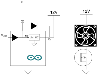
Arduino has on-board power regulator, which takes 6-12V and supply the chip with 5V power, and we could use it.
So we assembled the prototype, and now its a time to flash the firmware to Arduino. In order to do it, we need to connect it to USB.
Is it safe?
If we treat Arduino as a blackbox, it looks like safer to disconnect 12V power from the system, when connected to USB: to protect damage of computer by 12V power.
That's what I did. And got Arduino very hot. And I broke 3 boards, trying to found the issue.
The problem is that voltage regulator in Arduino is not designed to have power input at it's output, and low resistance load on it's input.
In our case fan has resistance of about 4 Ohm. When we connect USB power, there is current of up to 1 A going through voltage regulator and the fan. Which is OK for USB (it can supply up to 2.4 A) but dangerous for the regulator.
How to protect?
Depending on the desired functionality we can
- either block current flow in backward direction with diode,
- or let it bypass voltage regulator when flowing in backward direction
Links
https://arduinodiy.wordpress.com/2012/05/02/using-mosfets-with-ttl-levels/


Comments
Post a Comment